 You can create any kind of terrain you
can envision using 3rd PlanIt. The
terrain building process centers around Contour Lines, which provide elevation details for
the terrain (click for animation, 309K). Contour Lines are connected using the
Connect Tool, creating Terrain Sheets
made of small polygons.
You can create any kind of terrain you
can envision using 3rd PlanIt. The
terrain building process centers around Contour Lines, which provide elevation details for
the terrain (click for animation, 309K). Contour Lines are connected using the
Connect Tool, creating Terrain Sheets
made of small polygons.
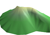 When rendered in 3D, the Terrain Sheets take on a very realistic look that
you can accentuate with creative light placement. Smooth
Shading and Color Blending are
used to refine the rendering and provide ground detail. You may position several lights in your drawing and adjust their color and brightness.
You can even set up spotlights to highlight areas of interest.
When rendered in 3D, the Terrain Sheets take on a very realistic look that
you can accentuate with creative light placement. Smooth
Shading and Color Blending are
used to refine the rendering and provide ground detail. You may position several lights in your drawing and adjust their color and brightness.
You can even set up spotlights to highlight areas of interest.
3rd PlanIt's terrain design system allows you to create simple or complex
landscapes depending on the level of detail you'd like to represent. You can
even enter contour lines from surveyed plans to provide the highest level of
accuracy, such as when designing a Garden Railroad.
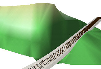
 The
terrain design is easily modified. Some designers like to enter terrain first,
then plan the railroad around it. Using the above hill as an example, we'll see
how to do that with 3rd PlanIt. The track that cuts through the hill is designed
and two sets of Ballast Contours are made. The narrow pair connects the
terrain to the Auto-Ballast, while the outer pair is used to slice the contour
lines that form the hill. Click to view
animation of contour slicing (2278K)
The
terrain design is easily modified. Some designers like to enter terrain first,
then plan the railroad around it. Using the above hill as an example, we'll see
how to do that with 3rd PlanIt. The track that cuts through the hill is designed
and two sets of Ballast Contours are made. The narrow pair connects the
terrain to the Auto-Ballast, while the outer pair is used to slice the contour
lines that form the hill. Click to view
animation of contour slicing (2278K)
 All
Contour Lines are selected at the same time, and the Slice
at Intersection tool is used to simultaneously slice them all with
the leftmost Ballast Contour. The sliced lines to the right are then sliced
again using the second Ballast Contour. New Edge Contour lines are
automatically created whenever you slice more than one Contour Line with
another. The Edge Contour can quickly be connected with the track's Ballast
Contour, and lies exactly where the cut terrain ends.
All
Contour Lines are selected at the same time, and the Slice
at Intersection tool is used to simultaneously slice them all with
the leftmost Ballast Contour. The sliced lines to the right are then sliced
again using the second Ballast Contour. New Edge Contour lines are
automatically created whenever you slice more than one Contour Line with
another. The Edge Contour can quickly be connected with the track's Ballast
Contour, and lies exactly where the cut terrain ends.
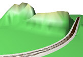
 The
Connect Terrain tool is used once again to
create the new terrain. After switching to 3D, you can see the cut through the
hillside, and the terrain extending right to the edge of the Auto-Ballast.
The
Connect Terrain tool is used once again to
create the new terrain. After switching to 3D, you can see the cut through the
hillside, and the terrain extending right to the edge of the Auto-Ballast.
Hillside with Cut
Click for animation (577K)
 This
flexible terrain modeling capability lets you create scenes of great complexity.
You can create mountain ranges by combining individual hills one over another.
When rendered in 3D, the hills intersect each other cleanly.
This
flexible terrain modeling capability lets you create scenes of great complexity.
You can create mountain ranges by combining individual hills one over another.
When rendered in 3D, the hills intersect each other cleanly.
If
you examine the 3D view in detail, you can see that each hill has different
shading. The hill on the right was designed with level contour lines to cause a
very regular change in color from top to bottom. The hill on the left had its
contour lines randomized before creating its terrain. This results in a less
regular change in coloration, as might result from uneven runoff.
Fractal
Plants
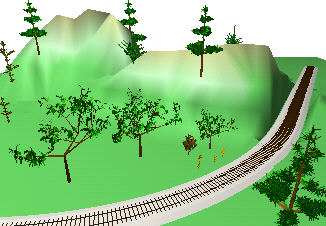 Every
model railroad needs plants on it, and a track plan begs for them as well. 3rd
PlanIt offers Fractal Plants to provide a wide assortment of plants, each
with its own style. While some trees are clearly redwoods, others are oaks, some
are weeds are bushes - no two plants look the same. You can even change the
fractal parameters to make plants of your own design. Click
to view animation of Engineer's View driving through cut in hill (351K)
Every
model railroad needs plants on it, and a track plan begs for them as well. 3rd
PlanIt offers Fractal Plants to provide a wide assortment of plants, each
with its own style. While some trees are clearly redwoods, others are oaks, some
are weeds are bushes - no two plants look the same. You can even change the
fractal parameters to make plants of your own design. Click
to view animation of Engineer's View driving through cut in hill (351K)